• home

Automatic Light Controller

     Voltage regulator ICs (78xx series) provide a steady output voltage, as against a widely fluctuating input supply, when the common terminal is grounded. Any voltage about zero volt (ground) connected in the common terminal is added to the output voltage. That means the increase in the common terminal voltage is reflected at the output. On the other hand, if the common terminal is disconnected from the ground, the full input voltage is available at the output.
www.blogger.com

     This characteristic is utilised in the present circuit. When the common terminal is connected to the ground, the regulator output is equivalent to the rated voltage, and as soon as the terminal is disconnected from the ground, the output increases up to the input voltage.

     The common terminal is controlled by a transistor, which works as a switch on the terminal. For automatic control of light, a light-dependent resistor (LDR1) is connected to the base of the transistor. In this way, the voltage regulator is able to operate a light bulb automatically as per the ambient light.

     To derive the power supply for the circuit, the 50Hz, 230V AC mains is stepped down by transformer X1 to deliver a secondary output of 12V, 250 mA. The secondary output of the transformer is applied to a bridge rectifier comprising diodes D1 through D4, filtered by capacitor C1 and fed to the input terminal of the regulator (IC1).

     The common terminal (pin 2) of IC1 is connected to the ground line of the circuit through transistor BC557 (T1). The transistor is biased by R2, R3, VR1 and LDR1. The grounding of IC1 is controlled by transistor T1, while light is sensed by LDR1. Using preset VR1, you can adjust the light-sensing level of transistor T1.

     The output of IC1 is fed to the base of transistor T2 (through resistor R4 and zener diode ZD1) and relay RL1. LED1 connected across the positive and ground supply lines acts as a power-‘on’ indicator.

      Normally, the resistance of LDR1 is low during daytime and high during nighttime. During daytime, when light falls on LDR1, pnp transistor T1 conducts. The common terminal of IC1 connects to the ground and IC1 outputs 6V. As a result, transistor T2 does not conduct and the relay remains de-energised. The light bulb remains ‘off’ as the mains connection is not completed through the relay contacts.

     During nighttime, when no light falls on LDR1, it offers a high resistance at the base junction of transistor T1. So the bias is greatly reduced and T1 doesn’t conduct. Effectively, this removes the common terminal of IC1 from ground and it directs the full input DC to the output. Transistor T2 conducts and the relay energises to light up the bulb as mains connection completes through the relay contacts.

     As LDR1 is in parallel to VR1+R3 combination, it effectively applies only half of the total resistance of the network formed by R3, VR1 and LDR1 to the junction at T1 in total darkness. In bright light, it greatly reduces the total effective resistance at the junction.

     The circuit is simple and can be assembled on a small gene r a l -purpos e PCB. Use a heat-sink for IC1. Make sure that LDR1 and the light bulb are well separated.

     The circuit can be used for streetlights, tubelights or any other home electrical lighting system that needs to be automated.

Smart Heater Controller

Minuscule circuit of the electronic heater controller presented here is built around the renowned 3-Pin Integrated Temperature Sensor LM35 (IC1) from NSC. Besides, a popular Bi Mos Op-amp CA3140 (IC2) is used to sense the status of the temperature sensor IC1, which also controls a solid-state switch formed by a high power Triac BT136(T1). Resistive type electric heater at the output of T1 turns to ON and to OFF states as instructed by the control circuit.

This gadget can be used as an efficient and safe heater in living rooms, incubators, heavy electric/electronic instrument etc. Normally, when the temperature is below a set value (Decided by multi-turn preset pot P1), voltage at the inverting input (pin2) of IC1 is lower than the level at the non-inverting terminal (pin3). So, the comparator output (at pin 6) of IC1 goes high and T1 is triggered to supply mains power to the desired heater element.

Electronic Heater Controller Circuit Schematic.


Note:

CA3140 (IC2) is highly sensitive to electrostatic discharge (ESD). Please follow proper IC Handling Procedures.

When the temperature increases above the set value, say 50-60 degree centigrade, the inverting pin of IC1 also goes above the non-inverting pin and hence the comparator output falls. This stops triggering of T1 preventing the mains supply from reaching the heater element. Fortunately, the threshold value is user-controllable and can be set anywhere between 0 to 100 Degree centigrade.

The circuit works off stable 9Volt dc supply, which may be derived from the mains supply using a standard ac mains adaptor (100mA at 9V) or using a traditional capacitive voltage divider assembly. You can find such power circuits elsewhere in this website.

10 Amp Solar Charge Controller

The SCC2 is a solar charge controller, its function is to regulate the power flowing from a photovoltaic panel into a rechargeable battery. It features easy setup with one potentiometer for the float voltage adjustment, an equalize function for periodic overcharging, and automatic temperature compensation for better charging over a range of temperatures.

10 Amp Solar Charge Controller  Circuit Diagram with Parts List


The goal of the circuit design was to make a charge controller with analog simplicity, high efficiency, and reliability. A medium power solar system can be built with a 12V solar panel up to 10 amps, the SCC2, and a rechargeable battery. The SCC2 works with lead acid, NiCD and NiMH batteries with ratings from less than one to several hundred amp-hours. With the appropriate parts selection, the SCC2 can be operated at 6V, 12V, 24V or other voltages.

Specifications:
  • Maximum solar panel current: 10 Amps
  • Night time battery drain current: approximately 1ma
  • Nominal battery voltage: 6V, 12V or 24V.
  • See the full SCC2 specifications for more information.
Theory:
The SCC2 acts as a medium power DC current switch between the + terminals of the PV and battery. Diode D1 prevents reverse night time current flow from the battery back to the PV panel.

When the PV voltage is high enough to charge the battery, zener diode D2 conducts and turns on transistor Q2. Q2 switches the power for the rest of the circuit on. The circuit is switched off at night. IC2 provides a 5 volt regulated voltage to power the comparator circuits, it also provides a reference voltage for comparator IC1a.

When the battery voltage is below the desired full voltage and needs charging, comparator IC1a turns on and activates Q1 and Q3, this allows the solar charging current to flow into the battery. Note that Q3 is a P-channel mosfet, this allows the circuit to be wired with a common ground for the solar panel and battery. The solar current loop is drawn in heavy lines on the schematic.

When the battery reaches the full charge point, IC1a operates as a comparator based schmidt trigger oscillator, it switches the solar current off and on. The switching causes the battery voltage to oscillate a few tens of millivolts above and below the desired set point. A rail-to-rail op-amp is required for proper operation, 741 style op-amps will not work in this circuit.

The red/green charging/full LED is driven between the output of IC1a and IC1b. IC1b has an inverted version of the IC1a signal. Pin 5 of IC1b only needs an approximate center point to work as an on-off comparator, it is connected to the varying IC1a pin 2 so that it does not require another reference divider circuit.

The resistors and thermistor on the input side of IC1a form a resistive bridge circuit that is used to compare the battery voltage to a reference voltage coming from IC2/R8/R9. The potentiometer adjusts the voltage point around which the circuit will oscillate on full charge. Resistor R7 adds positive feedback to IC1a for a schmidt trigger characteristic and C6 sets the maximum frequency of oscillation. The thermistor provides thermal compensation, as the temperature goes down, the float voltage setting goes up.

The equalize switch, S1a, forces the circuit on for intentional overcharging. Switch S1b and R1 can be used to select a different float voltage range, you can experiment with this by using different values of R1, typically R1 should be greater than 1M.

Alignment:
  • Start with a charged battery, connect the solar panel directly to the battery until the battery voltage is at or above the desired full setting, this also that the panel is capable of charging the battery.
  • While measuring the battery voltage, adjust VR1 clockwise to align the float voltage set point.  If the LED turns red before it reaches the desired float voltage, the battery will need to charge for a while.
  • When the battery is fully charged, it should be at the float voltage and the led should show alternating colors.
  • The float voltage should be set when the board and battery are at room temperature. Typical 12V set points are 13.8V for a gell cell and 14.5V for a wet cell.  For 6V, divide those by two, for 24V, multiply by 2.
  • Follow your battery manufacturers recommendations for the best settings.
  • Readjust the float voltage after the battery has reached a full charge.
  • The float voltage should be set when the circuit is at room temperature.
Use:
Connect the solar panel to the SCC2 solar panel input connectors, connect the battery to the SCC2 output connectors. Put the solar panel in the sun, and watch the battery charge up. Systems where the battery is frequently discharged way down should occasionally be run in equalize mode for a few hours or a full day. It is best to monitor the battery voltage during this operation, disable equalization if the battery voltage goes above 16V (12V version).

555 timer IC Based Simple Servo Controller

555 timer IC Based Simple Servo Controller555 timer IC Based Simple Servo Controller

Servos became valuable products for any variety of plans, like robotics, automation or only remotely controlling some thing, for example model vehicle steering. Theyre reasonably low-priced and also simple to have hold of, however controlling them can be a little challenging while they requrie specific moment to control the output to advance into a preferred position.

Almost all servos use a 50Hz refresh rate (20ms) for level a beat of among 1 and 2ms is required to control the output to advance among -45degrees and +45degrees.

THE 555 timer may be used to control the output using a simple circuit and modified employing a potentiometer.

The circuit is quite self instructive. We start using a 555 timer IC to build the pulse each 20ms which has a responsibility cycle of among 5 and 10% (1-2ms). All of the components employed are common components. You are able to drive several servos with the identical signal by using circuit to all or any have same output or create multiple driver circuits to control several servos to various outputs.

Servos run with a voltage among 5 and 6V, dont exceed this or you can injury them. Although the 555 timer could operate up to 15V.

Also be aware that servos require much current when commanding them also to maintain a location below load, this is around several amps! And so make notice of the while creating your electrical power supply.

Pump Controller For Solar Hot Water System

This circuit optimises the operation of a solar hot water system. When the water in the solar collector is hotter than the storage tank, the pump runs. The circuit comprises two LM335Z temperature sensors, a comparator and Mosfet. Sensor 1 connects to the solar collector panel while Sensor 2 connects to the hot water panel. Each sensor includes a trimpot to allow adjustment of the output level. In practice, VR1 and VR2 are adjusted so that both Sensor 1 and Sensor 2 have the same output voltage when they are at the same temperature. The Sensor outputs are monitored using comparator IC1.

When Sensor 1 produces a higher voltage than Sensor 2, which means that sensor 1 is at a higher temperature, pin 1 of IC1 goes high and drives the gate of Mosfet Q1. This in turn drives the pump motor. IC1 includes hysteresis so that the output does not oscillate when both sensors are producing a similar voltage. Hysteresis comprises the 1MO feedback resistor between output pin 1 and non-inverting input pin 3 and the input 1kO resistor. This provides a nominal 12mV hysteresis so that voltage at Sensor 1 or Sensor 2 must differ by 12mV for changes in the comparator output to occur.

Circuit diagram:
pump-controller-for-solar-hot water system
Pump Controller For Solar Hot Water System

Since the outputs of Sensor 1 and Sensor 2 change by about 10mV/°C, we could say that there is a degree of hysteresis in the comparator. Note that IC1 is a dual comparator with the second unit unused. Its inputs are tied to ground and pin 2 of IC1 respectively. This sets the pin 7 output high. Since the output is an open collector, it will be at a high impedance. Mosfet Q1 is rated at 60A and 60V and is suitable for driving inductive loads due to its avalanche suppression capability. This clamps any inductively induced voltages exceeding the voltage rating of the Mosfet.

The sensors are adjusted initially with both measuring the same temperature. This can be done at room temperature; adjust the trimpots so that the voltage between ground and the positive terminal reads the same for both sensors. If you wish, the sensors can be set to 10mV/°C change with the output referred to the Kelvin scale which is 273K at 0°C. So at 25°C, the sensor output should be set to (273 + 25 = 298) x 10mV or 2.98V.

Note:
The sensors will produce incorrect outputs if their leads are exposed to moisture and they should be protected with some neutral cure silicone sealant. The sensors can be mounted by clamping them directly to the outside surface of the solar collector and on an uninsulated section of the storage tank. The thermostat housing is usually a good position on the storage tank.


Source by : Streampowers

Making PC USB LCD controller project

USB controller LCDThis really a work that so cool if you like modif PC. So this is a USB interface for alphanumeric LCD display like 4 × 20 which can be controlled with LCD Smartie program. USB interface is implemented by using PIC18F2550 microcontroller, Using USB LCD modules. Below is a project of the USB LCD controller.
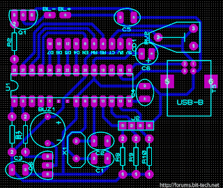


Schematic circuit and PCB design
Schematic USB control LCD

USB to control LCD from PC

source  | link