• home

Simple 12V DC to 220V 100W Inverter

Simple 12V DC to 220V 100W Inverter

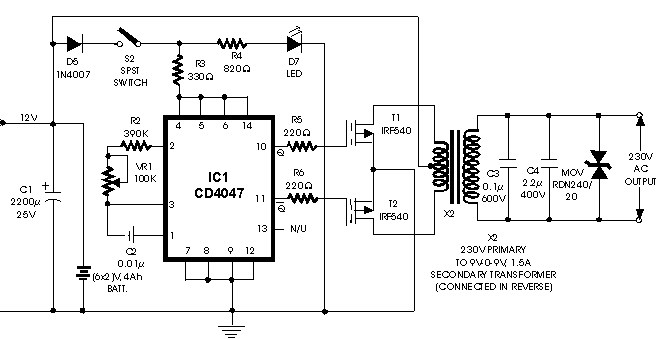
This is 100W inverter circuit. It uses 4047 IC and IRF540 Mosfet instead of 2N3055 transistor. Power output is 100W from 2-3A transformer. 


Surround Amplifier Circuit with TDA7053

Surround Amplifier Circuit with TDA7053

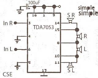
Perhaps the surround amplifier circuit below is an interesting circuit is made. For, making easy just by using the IC and electrolytic capacitor added 1 , we already can hear the strains of music with sound ( Front Left ,Right and surround Right , Left. In addition to listening to music , this amplifier is also very suitable for gamers who want good sound quality.

Surround amplifier circuit
Minimum voltage requred 9 volts and maximum of 15 volts. Power Output of each speaker 10 Watt with 4 ohm impedance.

Universal Constant Current Charger for Lead Acid Battery

Charge Termination

Once a battery is fully charged, the charging current has to be dissipated somehow. The result is the generation of heat and gasses both of which are bad for batteries. The essence of good charging is to be able to detect when the reconstitution of the active chemicals is complete and to stop the charging process before any damage is done while at all times maintaining the cell temperature within its safe limits. Detecting this cut off point and terminating the charge is critical in preserving battery life. In the simplest of chargers this is when a predetermined upper voltage limit, often called the termination voltage has been reached. This is particularly important with fast chargers where the danger of overcharging is greater.


Safe Charging

If for any reason there is a risk of over charging the battery, either from errors in determining the cut off point or from abuse this will normally be accompanied by a rise in temperature. Internal fault conditions within the battery or high ambient temperatures can also take a battery beyond its safe operating temperature limits. Elevated temperatures hasten the death of batteries and monitoring the cell temperature is a good way of detecting signs of trouble from a variety of causes. The temperature signal, or a resettable fuse, can be used to turn off or disconnect the charger when danger signs appear to avoid damaging the battery. This simple additional safety precaution is particularly important for high power batteries where the consequences of failure can be both serious and expensive.


Charging Times

During fast charging it is possible to pump electrical energy into the battery faster than the chemical process can react to it, with damaging results.

The chemical action can not take place instantaneously and there will be a reaction gradient in the bulk of the electrolyte between the electrodes with the electrolyte nearest to the electrodes being converted or "charged" before the electrolyte further away. This is particularly noticeable in high capacity cells which contain a large volume of electrolyte.

readmore from here http://www.mpoweruk.com/chargers.htm
Build a Programmable Amplifier circuit Diagram

Build a Programable Amplifier circuit Diagram . The intention of the following application shows how the NE5517 works in connection with a DAC. In the application, the NE5118 is used—an 8-bit DAC with current output—its input register making this device fully µ-compatible. The circuit consists of three functional blocks . The NE5118 which generates a control current equivalent to the applied data byte, a current mirror, and the NE5517 .

Build a Programmable Amplifier circuit Diagram

Build a Programmable Amplifier circuit Diagram

3 Rail Power supply Circuit Diagram

This 3- Rail Power supply Circuit Diagram generates three supply voltages using a minimum of components. Diodes D2 and D3 perform full-wave rectification, alternately charging capacitor C2 on both halves of the ac cycle. On the other hand, diode D1 with capacitor C1, and diode D4 with capacitor C3 each perform half-wave rectification. 

The full-and half-wave rectification arrangement is satisfactory for modest supply currents drawn from -5 and +12-V regulators IC3 and IC2. You can use this circuit as an auxiliary supply in an up-based instrument, for example, and avoid the less attractive alternatives of buying a custom-wound transformer, building a more complex supply, or using a secondary winding, say 18 Vac, and wasting power in the 5-V regulators.

3- Rail Power supply Circuit Diagram

3- Rail Power supply Circuit Diagram

Simple Car Battery Voltage Monitor Circuit

This circuit is used to monitor the battery voltage to display a dual-colored LED status of the battery to. If the LED “green”battery voltage exceeds 11.9 volts. If the yellow LED, battery voltage 11.9 to 11.5 volts. If the LED is “red” If the battery voltage below 11.5 volts. You can of course change the trigger points by the trimmer resistors and / or changing the value of the resistors in the divider.

Simple Car Battery Voltage Monitor Circuit

A dual op amp is used as a comparator. The green LED on the board, until the voltage exceeds 11.5 volts. The red LED illuminates when the voltage falls below 11.9 volts to the circuit. Therefore, in the 11.9 to 11.5 volts, both LEDs are on, producing a slightly yellow color. When the voltage falls below 11.5 V, the green LED, and now only the red LED flashes to indicate low voltage.

Electronic Parts List
R1=1K2
R2-3-4=680R
R5=15K
R6=10K
R7-8-9-10=1K
IC1=LM324
D1=5V6 /0.5W Zener
D2-3-4-5=LED
RV1=10K trimmer

Is recommended that multi-shaper for V1 and V2. Muti-trimmer makes it much easier to trigger points to make as a less expensive single-turn trimmer. The trimmer can be completely eliminated if you have access to a range of 1% resistors and has had calculated carefully. You would also want to provide more accurate reference voltage as the common 78L05 regulator.