• home

Automatic Light Controller

     Voltage regulator ICs (78xx series) provide a steady output voltage, as against a widely fluctuating input supply, when the common terminal is grounded. Any voltage about zero volt (ground) connected in the common terminal is added to the output voltage. That means the increase in the common terminal voltage is reflected at the output. On the other hand, if the common terminal is disconnected from the ground, the full input voltage is available at the output.
www.blogger.com

     This characteristic is utilised in the present circuit. When the common terminal is connected to the ground, the regulator output is equivalent to the rated voltage, and as soon as the terminal is disconnected from the ground, the output increases up to the input voltage.

     The common terminal is controlled by a transistor, which works as a switch on the terminal. For automatic control of light, a light-dependent resistor (LDR1) is connected to the base of the transistor. In this way, the voltage regulator is able to operate a light bulb automatically as per the ambient light.

     To derive the power supply for the circuit, the 50Hz, 230V AC mains is stepped down by transformer X1 to deliver a secondary output of 12V, 250 mA. The secondary output of the transformer is applied to a bridge rectifier comprising diodes D1 through D4, filtered by capacitor C1 and fed to the input terminal of the regulator (IC1).

     The common terminal (pin 2) of IC1 is connected to the ground line of the circuit through transistor BC557 (T1). The transistor is biased by R2, R3, VR1 and LDR1. The grounding of IC1 is controlled by transistor T1, while light is sensed by LDR1. Using preset VR1, you can adjust the light-sensing level of transistor T1.

     The output of IC1 is fed to the base of transistor T2 (through resistor R4 and zener diode ZD1) and relay RL1. LED1 connected across the positive and ground supply lines acts as a power-‘on’ indicator.

      Normally, the resistance of LDR1 is low during daytime and high during nighttime. During daytime, when light falls on LDR1, pnp transistor T1 conducts. The common terminal of IC1 connects to the ground and IC1 outputs 6V. As a result, transistor T2 does not conduct and the relay remains de-energised. The light bulb remains ‘off’ as the mains connection is not completed through the relay contacts.

     During nighttime, when no light falls on LDR1, it offers a high resistance at the base junction of transistor T1. So the bias is greatly reduced and T1 doesn’t conduct. Effectively, this removes the common terminal of IC1 from ground and it directs the full input DC to the output. Transistor T2 conducts and the relay energises to light up the bulb as mains connection completes through the relay contacts.

     As LDR1 is in parallel to VR1+R3 combination, it effectively applies only half of the total resistance of the network formed by R3, VR1 and LDR1 to the junction at T1 in total darkness. In bright light, it greatly reduces the total effective resistance at the junction.

     The circuit is simple and can be assembled on a small gene r a l -purpos e PCB. Use a heat-sink for IC1. Make sure that LDR1 and the light bulb are well separated.

     The circuit can be used for streetlights, tubelights or any other home electrical lighting system that needs to be automated.

Mini High Voltage Generator

Here’s a project that could be useful this summer on the beach, to stop anyone touching your things left on your beach towel while you’ve gone swimming; you might equally well use it at the office or workshop when you go back to work. In a very small space, and powered by simple primary cells or rechargeable batteries, the proposed circuit generates a low-energy, high voltage of the order of around 200 to 400 V, harmless to humans, of course, but still able to give a quite nasty ‘poke’ to anyone who touches it.  Quite apart from this practical aspect, this project will also prove instructional for younger hobbyists, enabling them to discover a circuit that all the ‘oldies’ who’ve worked in radio, and having enjoyed valve technology in particular, are bound to be familiar with. As the circuit diagram shows, the project is extremely simple, as it contains only a single active element, and then it’s only a fairly ordinary transistor. As shown here, it operates as a low-frequency oscillator, making it possible to convert the battery’s DC voltage into an AC voltage that can be stepped up via the transformer. 

Using a centre-tapped transformer as here makes it possible to build a ‘Hartley’ oscillator around transistor T1, which as we have indicated above was used a great deal in radio in that distant era when valves reigned supreme and these was no sign of silicon taking over and turning most electronics into ‘solid state’. The ‘Hartley’ is one of a number of L-C oscillator designs that made it to eternal fame and was named after its invertor, Ralph V.L Hartley (1888-1970). For such an oscillator to work and produce a proper sinewave output, the position of the intermediate tap on the winding used had to be carefully chosen to ensure the proper step-down (voltage reduction) ratio.  Here the step-down is obtained inductively. Here, optimum inductive tapping is not possible since we are using a standard, off-the-shelf transformer. However we’re in luck — as its position in the centre of the winding creates too much feedback, it ensures that the oscillator will always start reliably.

However, the excess feedback means that it doesn’t generate sinewaves; indeed, far from it. But that’s not important for this sort of application, and the transformer copes very well with it.  The output voltage may be used directly, via the two current-limiting resistors R2 an R3, which must not under any circum-stances be omitted or modified, as they are what make the circuit safe. You will then get around 200 V peak-to-peak, which is already quite unpleasant to touch. But you can also use a voltage doubler, shown at the bottom right of the figure, which will then produce around 300 V, even more unpleasant to touch. Here too of course, the resistors, now know as R4 and R5, must always be present. The circuit only consumes around a few tens of mA, regardless of whether it is ‘warding off’ someone or not! If you have to use it for long periods, we would however recommend powering it from AAA size Ni-MH batteries in groups of ten in a suitable holder, in order not to ruin you buying dry batteries.

Mini High-Voltage Generator Circuit diagram:


Warning!

If you build the version without the voltage doubler and measure the output voltage with your multimeter, you’ll see a lower value than stated. This is due to the fact that the waveform is a long way from being a sinewave, and multimeters have trouble interpreting its RMS (root-mean-square) value. However, if you have access to an oscilloscope capable of handling a few hundred volts on its input, you’ll be able to see the true values as stated. If you’re still not convinced, all you need do is touch the output terminals...

To use this project to protect the handle of your beach bag or your attachecase, for example, all you need do is fix to this two small metallic areas, quite close together, each connected to one output terminal of the circuit. Arrange them in such a way that unwanted hands are bound to touch both of them together; the result is guaranteed! Just take care to avoid getting caught in your own trap when you take your bag to turn the circuit off!

..::: Do not built this circuit if your not an EXPERT :::..

Source :  http://www.ecircuitslab.com/2011/07/mini-high-voltage-generator.html

PC Power Box with E fuse

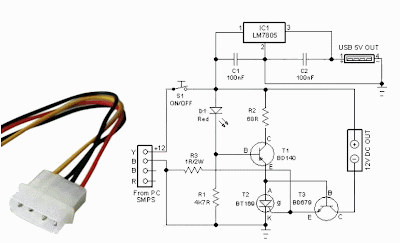
This little circuit will help you to remove all surplus small ac mains adaptors from your desktop. The circuit is nothing, but a smart dc power box directly powered by the smps of your desktop personal computer. Regulated, clean and protected +12VDC is available at the output of this unit. In addition, a USB power port is provided to re-charge portable devices including cellphones and music players, etc.

How does the pc power box works
All you need is to open your system box and connect an unused 4-pin drive power connector from the system smpsu to this circuit. +12V (Yellow wire) from the smps is processed by a resettable electronic fuse built around components T1, T2 and T3 and feed to the output terminal. Similarly the +12V is down converted to stable +5V by fixed 3 pin regulator IC1.

Smart dc power box circuit schematic

Circuit Project: PC Power Box with E-fuse

As a result, +12V (500 -750mA max, based on the electrical characteristics of T2 used) and +5V (1A max) DC supplies are available for external use, without affecting the normal pc functions. Switch S1 is the power on/off cum reset switch. Resistor R3 sets the maximum allowable output current rate and T1 disables the output power switch T3, when output load current exceeds the set value.

Simple Oscillator Pipe Locator

Sometimes the need arises to construct a really simple oscillator. This could hardly be simpler than the circuit shown here, which uses just three components, and offers five separate octaves, beginning around Middle C (Stage 14). Octave # 5 is missing, due to the famous (or infamous) missing Stage 11 of the 4060B IC. We might call this a Colpitts ‘L’ oscillator, without the ‘C’. Due to the reactance of the 100-µH inductor and the propagation delay of the internal oscillator, oscillation is set up around 5 MHz. When this is divided down, Stage 14 approaches the frequency of Middle C (Middle C = 261.626 Hz). Stages 13, 12, 10, and 9 provide higher octaves, with Stages 8 to 4 being in the region of ultrasound.

Simple Oscillator/Pipe Locator Circuit Diagram

Simple Oscillator-Pipe Locator-Circuit Diagram

If the oscillator’s output is taken to the aerial of a Medium Wave Radio, L1 may serve as the search coil of a Pipe Locator, with a range of about 50 mm. This is tuned by finding a suitable hetero-dyne (beat note) on the medium wave band. In that case, piezo sounder Bz1 is omitted. The Simple Oscillator / Pipe Locator draws around 7 mA from a 9-12 V DC source.


Source:  http://www.ecircuitslab.com/2012/05/simple-oscillator-pipe-locator.html

Smart Heater Controller

Minuscule circuit of the electronic heater controller presented here is built around the renowned 3-Pin Integrated Temperature Sensor LM35 (IC1) from NSC. Besides, a popular Bi Mos Op-amp CA3140 (IC2) is used to sense the status of the temperature sensor IC1, which also controls a solid-state switch formed by a high power Triac BT136(T1). Resistive type electric heater at the output of T1 turns to ON and to OFF states as instructed by the control circuit.

This gadget can be used as an efficient and safe heater in living rooms, incubators, heavy electric/electronic instrument etc. Normally, when the temperature is below a set value (Decided by multi-turn preset pot P1), voltage at the inverting input (pin2) of IC1 is lower than the level at the non-inverting terminal (pin3). So, the comparator output (at pin 6) of IC1 goes high and T1 is triggered to supply mains power to the desired heater element.

Electronic Heater Controller Circuit Schematic.


Note:

CA3140 (IC2) is highly sensitive to electrostatic discharge (ESD). Please follow proper IC Handling Procedures.

When the temperature increases above the set value, say 50-60 degree centigrade, the inverting pin of IC1 also goes above the non-inverting pin and hence the comparator output falls. This stops triggering of T1 preventing the mains supply from reaching the heater element. Fortunately, the threshold value is user-controllable and can be set anywhere between 0 to 100 Degree centigrade.

The circuit works off stable 9Volt dc supply, which may be derived from the mains supply using a standard ac mains adaptor (100mA at 9V) or using a traditional capacitive voltage divider assembly. You can find such power circuits elsewhere in this website.

USB Power Booster

Power shortage problems arise when too many USB devices connected to PC are working simultaneously. All USB devices, such as scanners, modems, thermal printers, mice, USB hubs, external storage devices and other digital devices obtain their power from PC. Since a PC can only supply limited power to USB devices, external power may have to be added to keep all these power hungry devices happy. This circuit is designed to add more power to a USB cable line.

A sealed 12V 750 mA unregulated wall cube is cheap and safe. To convert 12 V to 5 V, two types of regulators, switching and linear are available with their own advantages and drawbacks. The switching regulator is more suitable to this circuit because of high efficiency and compactness and now most digital circuits are immune to voltage ripple developed during switching. The simple switcher type LM2575-5 is chosen to provide a stable 5V output voltage.

USB Power Booster Circuit Diagram

This switcher is so simple it just needs three components: an inductor, a capacitor and a high-speed or fast-recovery diode. Its principle is that internal power transistor switch on and off according to a feedback signal. This chopped or switched voltage is converted to DC with a small amount of ripple by D1, L1 and C2. The LM2575 has an ON/OFF pin that is switched on by pulling it to ground.

T1, R2, and R1 (pull-up resistor) pull the ON/OFF pin to ground when power signal from PC or +5 V is received. D2, a red LED with current resistor R3, serves to indicate ‘good’ power condition or stable 5V. C3 is a high-frequency decoupling capacitor. The author managed to cut a USB cable in half without actually cutting data wires. It is advisable to look at the USB cable pin assignment for safety.
Circuit Source: DIY Electronics Projects

12v to 5v dc dc converter circuit diagram

Power supply is needed for all of electronic circuits. Say you have a 12V power supply and you want to use it as a 5V power supply. Then use this 12v to 5v dc-dc converter circuit diagram to convert 12 volt to 5 volt. This DC converter circuit provide 5V, 1Amp at output. Here is the small schematic circuit diagram of 12volt to 5volt converter.

Circuit Diagram of 12VDC to 5VDC converter:


12v to 5v converter
Fig: 12 volt to 5 volt dc converter circuit schematic

This DC-DC converter is based on IC LM7805. The LM 7805 is a 3-terminal fixed output positive voltage regulator IC. The output current of this circuit is up to 1Amp . Use a heat sink with LM7805 to protect the IC from overheating.