• home

12v to 5v dc dc converter circuit diagram

Power supply is needed for all of electronic circuits. Say you have a 12V power supply and you want to use it as a 5V power supply. Then use this 12v to 5v dc-dc converter circuit diagram to convert 12 volt to 5 volt. This DC converter circuit provide 5V, 1Amp at output. Here is the small schematic circuit diagram of 12volt to 5volt converter.

Circuit Diagram of 12VDC to 5VDC converter:


12v to 5v converter
Fig: 12 volt to 5 volt dc converter circuit schematic

This DC-DC converter is based on IC LM7805. The LM 7805 is a 3-terminal fixed output positive voltage regulator IC. The output current of this circuit is up to 1Amp . Use a heat sink with LM7805 to protect the IC from overheating.

Build a Period To Voltage Converter Circuit Diagram

The input signal drives ICD. Because ICD`s positive input (V+) is slightly offset to + 0.1 V, its steady stateoutput will be around +13 V. This voltage is sent to ICC through D2, setting ICC`s output to +13 V. Therefore, point D is cut off by Dl, and CI is charged by the current source. Assuming the initial voltage on CI is zero, the maximum voltage (^Cinax) is given by: 

When the input goes from low to high, a narrow positive pulse is generated at point A. This pulse becomes -13 V at point B, which cuts off D2. ICC`s V+ voltage becomes zero. The charge on CI will be absorbed by ICC on in a short time. 

The time constant of C2 and R5 determines the discharge period— about 10 /is. ICB is a buffer whose gain is equal to (R& + R9)~Rg = lM5. ICD`s average voltage will be (1362f 1.545) + 2 = 1052/. RIO and C3 smooth the sawtooth waveform to a dc output.


Period-To-Voltage Converter Circuit Diagram

Period-To-Voltage Converter Circuit Diagram


Build a Period-To-Voltage Converter Circuit Diagram

How to Make a Simplest Triac Dimmer Switch Circuit

We have already seen in many of my earlier articles how triacs are used in electronic circuits for switching AC loads.
Triacs are basically devices which are able to switch ON a particular connected load in response to an external DC trigger.
Though these may be incorporated for complete switch ON and complete switch OFF procedures of a load, the device is also popularly applied for regulating an AC, such that the output to the load may be reduced to any desired value.
For example triacs are very commonly used dimmer switch applications where the circuit is designed to make the device switch in such a manner that it conducts only for a particular section of the AC sine wave and remains cut OFF during the remaining parts of the sine wave.
This result is an corresponding output AC which has an average RMS value much lower than the actual input AC.
The connected load also responds to this lower value AC and is thus controlled to that particular consumption or resultant output.
This is what exactly happens inside electrical dimmer switches which are normally used for controlling ceiling fan and incandescent lights.

Simple and the Best Triac Dimmer Switch Circuit

The circuit diagram shown above is an classic example of a dimmer switch, where a triac has been utilized for controlling the intensity of light.
When AC mains is fed to the above circuit, as per the setting of the pot, C2 charges fully after a particular delay providing the necessary firing voltage to the diac.
The diac conducts and triggers the triac into conduction, however this also discharges the capacitor whose charge reduces below the diacs firing voltage.
Due to this the diac stops conducting and so does the triac.
This happens for each cycle of the mains AC sine wave signal, which cuts it into discrete sections, resulting in well tailored lower voltage output.
The setting of the pot sets the charge and the discharge timing of C2 which in turn decides for how long the triac remains in a conducting mode for the AC sine signals.
You might be interested to know why C1 is placed in the circuit, because the circuit would work even without it.
Its true, C1 is actually not required if the connected load is a resistive load like an incandescent lamp etc.
However if the load is an inductive type, the inclusion of C1 becomes very crucial.
Inductive loads have a bad habit of returning a part of the stored energy in the winding, back into the supply rails.
This situation can choke up C2 which then becomes unable to charge properly for initiating the next subsequent triggering.
C1 in this situation helps C2 to maintain is cycle by providing bursts of small voltages even after C2 has completely discharged, and thus maintains the correct switching rate of the triac.
Triac dimmer circuits have the property of generating a lot of RF disturbances in the air while operating and therefore an RC network becomes imperative with these dimmer switches for reducing the RF generations. The above circuit is shown without the feature and therefore will generate a lot of RF which might disturb sophisticated electronic audio systems.
The circuit of a dimmer switch illustrated below incorporate the necessary precautions for subsiding the above issue.


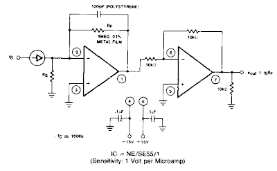
Current to Voltage Converter Circuit Diagram

A filter removes the dc component of the rectified ac, which is then scaled to RMS. The output is linear from 40 Hz to 10 kHz or higher.

 Current to Voltage Converter Circuit Diagram

Current to Voltage Converter Circuit Diagram

2007 Toyota Prius How to Replace the Rear Wiper Blades


How can I replace the rear wiper blade assembly on my 2007 Toyota Prius, (not only the rubber insert) How to detach the blade assembly from the wiper arm? Does anyone have a suggestion?

Answer: As far as I know,  the size of the rear wiper blade  on the 2007 Toyota Prius is unique, it is very specific. My suggestion is go to the parts department in your local Toyota dealership to find the right insert that fits the blade assembly, so you don’t have to detach the blade assembly. Good luck.

Simple 12V DC to 220V 100W Inverter

Simple 12V DC to 220V 100W Inverter

This is 100W inverter circuit. It uses 4047 IC and IRF540 Mosfet instead of 2N3055 transistor. Power output is 100W from 2-3A transformer. 


Speaker to microphone converter circuit


This circuit is a simple approach for converting a loud speaker into a microphone. When the sound waves fall on the diaphragm of a speaker, there will be fluctuations in the coil and there will be a small proportional induced voltage. Usually this induced voltage is very low in magnitude and useless. Here in the circuit the low voltage is amplified using transistors to produce a reasonable output. The transistor Q1 is wired in common base mode and produces the required voltage gain. The transistor Q2 is wired as an emitter follower to produce enough current gain. The voice quality of this circuit will not be as much as a conventional microphone but quite reasonable quality can be obtained. To set up the circuit, keep the preset R2 at around 10 Ohms and connect the battery. Now adjust R2 to obtain the optimum sound quality.

Notes.

* Assemble the circuit on a general purpose PCB. * Power the circuit from a 9 V PP3 battery. * A 3 inch speaker can be used as K1. * All capacitors must be rated at least 15V. * An 8 Ohm speaker or head phone can be connected at the output to hear the picked sound.

4 Bit Analogue to Digital Converter

The operation of the converter is based on the weighted adding and transferring of the analogue input levels and the digital output levels. It consists of comparators and resistors. In theory, the number of bits is unlimited, but each bit needs a comparator and several coupling resistors. The diagram shows a 4-bit version. The value of the resistors must meet the following criteria:
  • R1:R2 = 1:2;
  • R3:R4:R5 = 1:2:4;
  • R6:R7:R8:R9 = 1:2:4:8.
The linearity of the converter depends on the degree of precision of the value of the resistors with respect to the resolution of the converter, and on the accuracy of the threshold voltage of the comparators. This threshold level must be equal, or nearly so, to half the supply voltage. Moreover, the comparators must have as low an output resistance as possible and as high an input resistance with respect to the load resistors as feasible. Any deviation from these requirements affects the linearity of the converter adversely.
Circuit diagram:
4-bit_AnalogueTo_Digital_Converter-Circuit-Diagramw
4-Bit Analogue to Digital Converter Circuit Diagram

If the value of the resistors is not too low, the use of inverters with an FET (field-effect transistor) input leads to a near-ideal situation. In the present converter, complementary metal-oxide semiconductor (CMOS) inverters are used, which, in spite of their low gain, give a reasonably good performance. If standard comparators are used, take into account the output voltage range and make sure that the potential at their non-inverting inputs is set to half the supply voltage. If high accuracy is a must, comparators Type TLC3074 or similar should be used. This type has a totem-pole output. The non-inverting inputs should be interlinked and connected to the tap of a a divider consisting of two 10 kΩ resistors across the supply lines. It is essential that the converter is driven by a low-resistance source. If necessary, this can be arranged via a suitable op amp input buffer. The converter draws a current not exceeding 5 mA.
 
 
Source :www.ecircuitslab.com
 

Simple 240VAC TO 5VDC POWER SUPPLY

This is simple way to power some 5v logic from a 240vac source. If a 120vac power adapter is used, the circuit will also work for 120vac power lines.
 
 
240VAC TO 5VDC POWER SUPPLY,

How to Make an Automatic Vehicle Headlight Dipper Dimmer Circuit

The circuit described here can be built and used in your vehicle for an automatic dipping and dimming operation of the headlamps, in response to the intense lights coming from an opposite vehicle headlamps.


More innovative circuits HERE.

You must have come across this irritating situation while driving at night when you find the headlight focus from an opposite vehicle falling straight in your eyes, making things difficult to assess, giving rise to a situation of a collision or some kind of possible accident.

Incidentally, the driver of the opposite vehicle might be going through the same situation due to the headlight focus from your vehicle.

Such situations are normally tackled by using manual dipper switch mechanism, where the driver is prompted to "dip" the focus of his headlight, thus giving the opposite vehicle a chance to adjust his vehicle and also an indication that he too needs to "dip" his vehicle lamps.


However, doing the above operation manually, every now and then can become horribly laborious and troublesome, therefore if some kind of automatic system is Incorporated, can help to save this headache of the driver, especially while he is driving in stressful conditions and on dangerous highways.

How to make an automatic vehicle headlight dipper/dimmer circuit

The following diagram describes a simple yet effective auto head lamp dipper or dimmer circuit. The transistor is used as a comparator, which compares the preset resistance level and the LDR resistance level with reference to ground.


Light falling over the LDR from the headlight of the vehicle coming from the front instantly lowers its resistance and allows more current to flow to the base of the transistor.

The transistor conducts and activates the relay, which in turn flips the contacts such that the host vehicles headlamps gets connected with the dipper filament, changing its intensity.

The whole circuit may be enclosed in a small box and installed somewhere near the drivers dashboard area, however the LDR needs to be wired and placed out of the enclosure, in some corner of the wind shield, so that it is able to "see the light from the opposite vehicles just as the driver would see them.

Parts List

R1 = 1K,
P1 = 10 K,
LDR = With resistance @ around 10 to 50 K when illuminated in daylight (under shade).
T1 = BC547,
D1 = 1N4007
Relay = coil 400 Ohms, DPDT, 12 volts