• home

PC Power Box with E fuse

This little circuit will help you to remove all surplus small ac mains adaptors from your desktop. The circuit is nothing, but a smart dc power box directly powered by the smps of your desktop personal computer. Regulated, clean and protected +12VDC is available at the output of this unit. In addition, a USB power port is provided to re-charge portable devices including cellphones and music players, etc.

How does the pc power box works
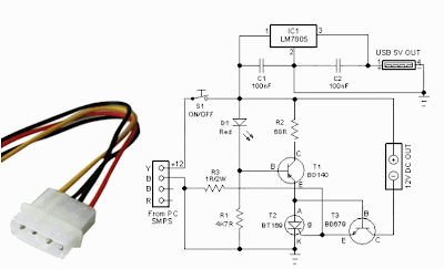
All you need is to open your system box and connect an unused 4-pin drive power connector from the system smpsu to this circuit. +12V (Yellow wire) from the smps is processed by a resettable electronic fuse built around components T1, T2 and T3 and feed to the output terminal. Similarly the +12V is down converted to stable +5V by fixed 3 pin regulator IC1.

Smart dc power box circuit schematic
Circuit Project: PC Power Box with E-fuse

As a result, +12V (500 -750mA max, based on the electrical characteristics of T2 used) and +5V (1A max) DC supplies are available for external use, without affecting the normal pc functions. Switch S1 is the power on/off cum reset switch. Resistor R3 sets the maximum allowable output current rate and T1 disables the output power switch T3, when output load current exceeds the set value.

Fuse Box BMW 1984 528I Diagram

Fuse Box BMW 1984 528I Diagram - Here are new post for Fuse Box BMW 1984 528I Diagram.

Fuse Box BMW 1984 528I Diagram


Fuse Box BMW 1984 528I Diagram

Fuse Panel Layout Diagram Parts: low beam relay, fog light relay, main relay, purge valve relay, normal speed relay, high speed relay, low beam check relay, high beam relay, fuel pump relay, horn relay, wiper control unit, unloader relay.

Fuse Box 1991 BMW 325i Diagram

Fuse Box 1991 BMW 325i Diagram - Here are new post for Fuse Box 1991 BMW 325i Diagram.

Fuse Box 1991 BMW 325i Diagram


Fuse Box 1991 BMW 325i Diagram

Fuse Panel Layout Diagram Parts: Headlights, High beam indicator, Headlights, Auxiliary fan, Lights/Turn hazard warning, Active check control, Glove box light, Electro-mechanical convertible top, Wiper/washer, Stop lights/cruise control, Active check control, Antilock braking system, Cruise control, Map reading light, Rear defogger, Injection electronics, Ignition key warning/seatbelt warning, back-up lights, Tachometer/Fuel economy gauges, Injection electronics, Brake warning system, Cruise control, Injection electronics, adio, speedometer, on-board computer, Headlights, Heated seats, Power windows, Auxiliary fan, Interior Lights, Power mirrors, Heater/Air conditioning, Auxiliary fan.

Fuse BOx BMW Z3 Underdash 1996 Diagram

Fuse BOx BMW Z3 Underdash 1996 Diagram - Here are new post for Fuse BOx BMW Z3 Underdash 1996 Diagram.

Fuse BOx BMW Z3 Underdash 1996 Diagram


Fuse BOx BMW Z3 Underdash 1996 Diagram

Fuse Panel Layout Diagram Parts: ABS system, motorsport, airbag, air conditioning, automatic transmission, anti theft sytem, cigar lighter, clock, connector for optional, cruise control, cruise seats adjustment, electronic immobilizer, exhausy gas diagnosis, fuel pump, headlight cleaning system, heated seat window, heated blower, brake light, parking light, reversing light, side ligth, low beam headlight, interior light, high beam headlight.

Type and function of subwoofer speaker box

Know Your Types of box type subwoofer
Performance subwoofer to produce low bass sound and also solid course supported by a subwoofer enclosure or box. Subwoofer box in the car usually has a different size, it is adjusted to the recommendations of the technical data from these subwoofers. However, each audio installer, have different styles in a box design.
If all this time, we only know when the box was just the type thats all, it did not. Box consists of various types and models. Design, size (dimensions) and a subwoofer box models are usually clearly taken into account at the time of manufacture, even carefully designed too often acted the Installer. Clearly, each type of box has a value of strengths and weaknesses, all models of boxes, if applied correctly, clearly gives a very maximum performance subwoofer.
subwoofer speaker system
Following this, the types of subwoofer box that is often applied in car audio:
If you want us to categorize the type of subwoofer box can be divided according to several orders of more detail:
• Second Order / Infinite Baffle / Free Air
• Typical Rear Deck Installation / Infinite Baffle / Free
• Back Seat Installation
• Small Deck Installation
• Second Order / Acoustic Suspension / Sealed enclosures
• Sealed
• isobaric - Sealed
• isobaric - Sealed (Compound Loading)
• isobaric - Sealed (Back to Back)
• isobaric - Sealed (Planar Loading)
• Fourth Order / Bass Reflex & bandpass enclosures
• Fourth Order / Bass Reflex
• isobaric - Bass Reflex
• isobaric - Bass Reflex (Compound Loading)
• Bass Reflex - Passive Radiator
• isobaric Bass Reflex - Passive Radiator
• Single Reflex - Band Pass
• Single Reflex isobaric bandpass
• Three Chamber Single Reflex bandpass
• Three Chamber Single Reflex isobaric bandpass
• Sixth Order enclosures
• Quasi Sixth Order Series-Tuned bandpass
• isobaric Quasi Sixth Order Series-Tuned bandpass
• Dual reflex bandpass
• Dual Reflex isobaric bandpass
• Three Chamber Dual Reflex bandpass
• Three Chamber Dual Reflex isobaric bandpass
• Eighth Order enclosures
• Quasi Eighth Order Series-Tuned Dual Reflex bandpass
• Quasi isobaric Eighth Order Series-Tuned Dual Reflex bandpass
• Eighth Order Triple Reflex bandpass
• Eighth Order Triple Reflex isobaric bandpass

Fuse Box Toyota 1985 Celica Engine Compartment Diagram

Fuse Box Toyota 1985 Celica Engine Compartment Diagram - Here are new post for Fuse Box Toyota 1985 Celica Engine Compartment Diagram.

Fuse Box Toyota 1985 Celica Engine Compartment Diagram


Fuse Box Toyota 1985 Celica Engine Compartment Diagram

Fuse Panel Layout Diagram Parts: headlight control relay, fan relay, radio, RTR, engine main relay, Head lamp, hazzard, horn, charge relay, headlamp, EFI main relay.

Spy Camera Solar Power Box

Battery life has always been a critical consideration for most of the electronic gadgets and equipment. When we talk about spy  cameras,  which  normally  function  round-the-clock, they often run out of power within a few days.  Many spy cameras (CCTV cameras) are powered by 9V PP3 type batteries that offer five times more energy  than the regular 9V alkaline battery.

Mini CCTV cameras also accept 6-12V DC supply from AC mains adaptor through the DC IN jack. AC mains adaptor for the camera increases the capacity of the 9V PP3 battery but is bulky and noisy. Whether disposable  or rechargeable batteries, making frequent replacement or recharging them is a cumbersome job. The unique solar power box described here serves an alternative solution to the problem. 

Spy Camera Solar Power Box Circuit diagram :

Spy Camera Solar Power Box-Circuit Daigram

The circuit of the solar power box is simple. It contains a  battery charger and a battery health indicator and  a few other components.  As shown in the circuit,  DC supply available from  the solar panel (SP1) is  directly applied to the in-put of the circuit through  a protection diode (D1).  This diode is used to pre-vent  the  reverse  current  flow from the battery to  the  solar  panel  during  night. Thus, D1 allows  the current to flow from the solar panel  to the battery only. Low-voltage-drop  type 1N5817 diode is perfect for the  job.
At the heart of the circuit is an integrated current source, realised using a  popular 3-pin adjustable voltage regulator LM317T(IC1). 

This IC is designed  to adjust its internal resistance between  the In (pin 3) and Out (pin 2) terminals  to maintain a constant voltage of 1.25V  between the Out (pin 2) and Adj (pin 1) terminals. Here, a 9V, 280 mAh  rechargeable PP3 type Ni-MH battery  (BATT) is used as reservoir. Normally,  a charging current of about 10 per cent  of  ampere-hour  rating  is  safe  for  the  battery. Resistor R1 (39-ohm, 0.5W),  connected between pin 1 and 3 of IC1,  limits  the  charging  current  to  about  30 mA. DC output from the battery is  available at output jack J2. Red LED  ( LED1) is used as a battery ‘health’  indicator. Switch S1 is used to start the  charging while S2 is used for connect-ing the load. Note that suitable heat  sink should be used for the IC1.

The proper selection of solar panel  is important but not critical. A miniature 12V type solar panel with a cur-rent output of about 100 mA can be  used. Even if you have a solar panel  with  higher  voltage  rating,  it  will  not  create a problem as the circuit ensures  that the charging current cannot exceed  the predetermined value.

The circuit can be easily assembled  on a general-purpose PCB and housed  in a small plastic cabinet.

Source :  http://www.ecircuitslab.com/2012/05/spy-camera-solar-power-box.html